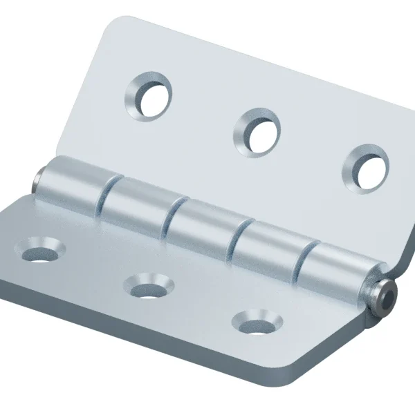
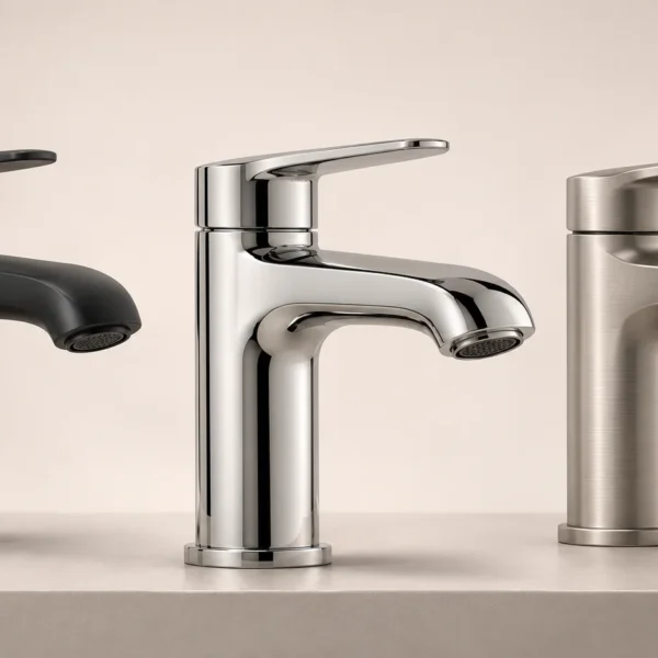
AI product modeling can help, but start with what you need to deliver. The three outputs are different: a photorealistic image, a 3D model you can rotate and edit, and a CAD file you can check before manufacturing. A result that looks right in a catalogue cannot tell you whether the mounting holes will line up.
AI product modeling: image, mesh or CAD?
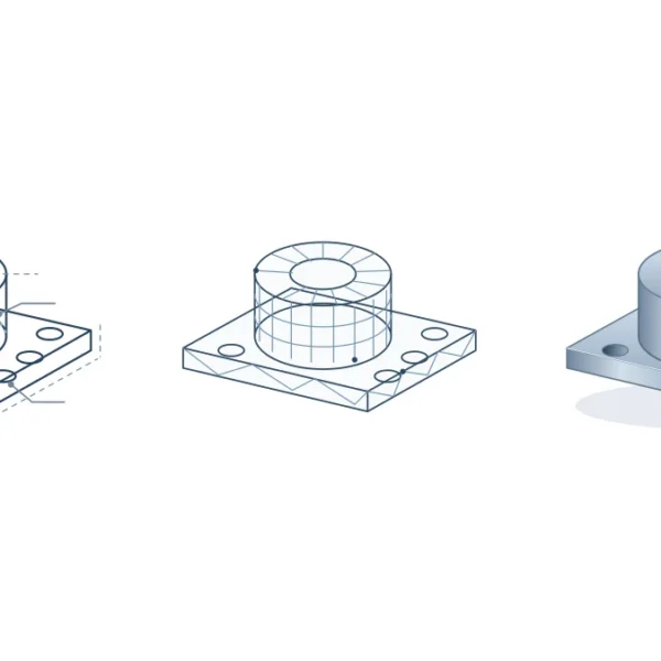
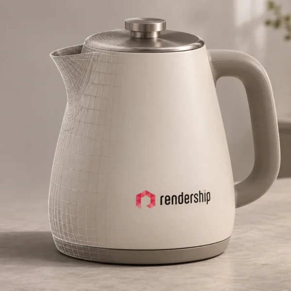
- A product image contains pixels, not geometry. It can help you explore composition, material appearance or a setting from one view. You cannot rotate the object or measure a hole in the image. Generating a second view is not the same as rotating the same 3D object.
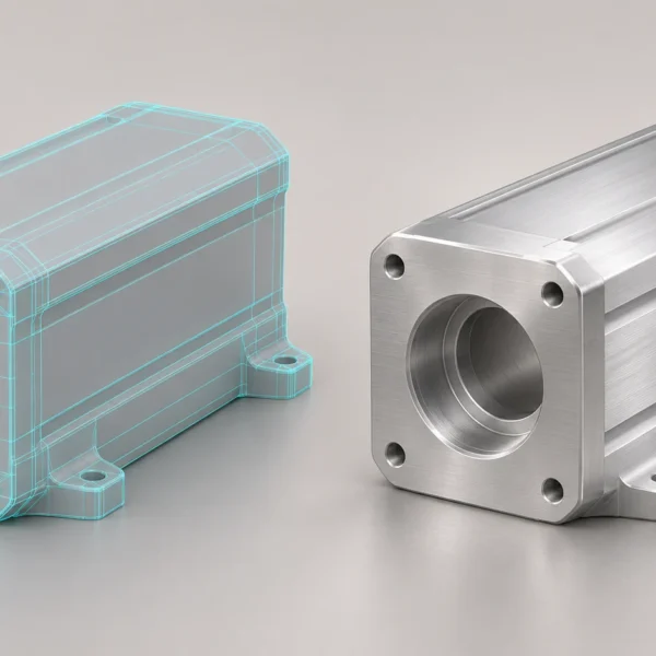
- An editable mesh has vertices, edges and faces. Open it in a 3D editor and you can select and change its geometry, rotate it, or light it from another angle. Being editable does not make it dimensionally accurate.
- A CAD model intended for manufacturing represents dimensions, hole axes and design relationships. Material, process, tolerances, assembly fit and drawings still need appropriate technical review. Converting a mesh to a solid does not recover measurements or design intent. Autodesk’s mesh conversion documentation shows that a faceted conversion can preserve individual mesh faces as separate faces of the resulting body.
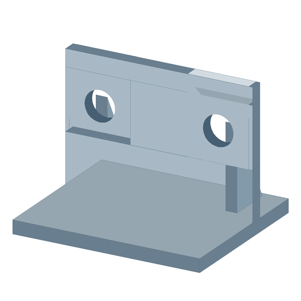
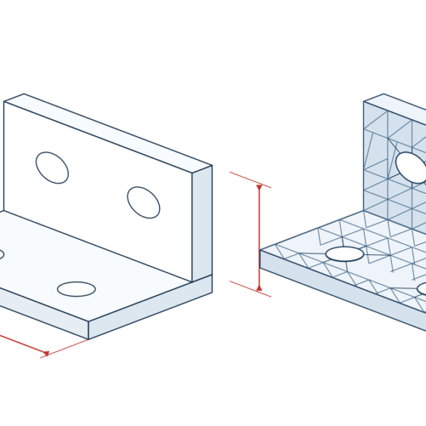
Fixed-camera example: a mounting bracket with two holes
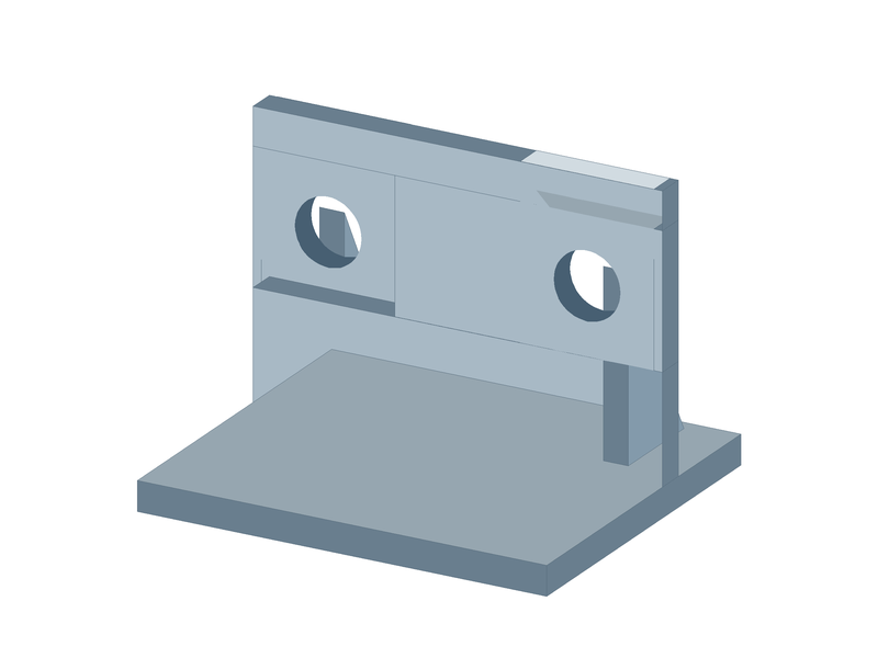
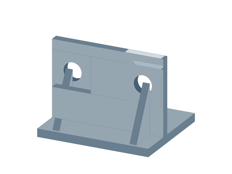
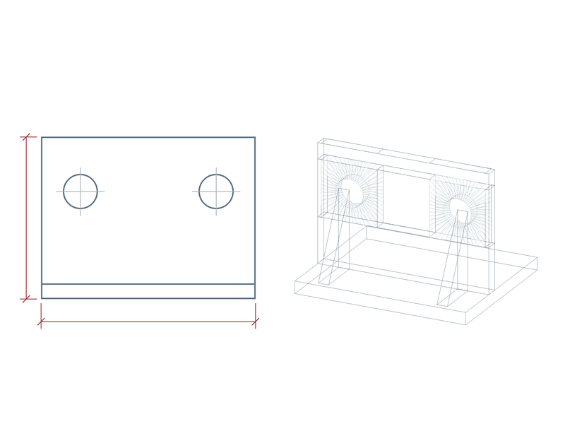
This is a hypothetical part, not a client project or an AI performance test. Suppose an L bracket measures 120 mm across, the plate is 4 mm thick, and the two front holes are 8 mm in diameter. We have front, side, top and rear reference photographs with a scale reference. To check the front silhouette in the model, we set up a front orthographic camera and lock its angle, scale, crop and aspect ratio. We do not overlay a perspective photograph on an orthographic view as if they shared a projection. Instead, match the camera perspective or take a calibrated reference photo of the surface you want to check.
First we overlay the front silhouette and compare the hole positions. A good match from the front does not tell us whether the holes go all the way through. We check plate thickness and the bend from the side, any reinforcement from the rear, and the bores in section. We measure hole spacing and distance from the edges separately. If the bend radius or a hidden reinforcement detail is unknown, we do not turn a guess into a dimension.
From a rough 3D output to a model you can use
- Establish scale. Set the file units and use a reliable dimension to set the scale. The bracket’s 120 mm overall width does not prove the rest is correct; verify the 4 mm thickness and 8 mm holes independently.
- Check the geometry against the references. Compare the front, side, top and rear. Look for evidence for the silhouette, thickness, through-holes, joints and hidden surfaces. Ask for another photograph, a physical measurement or a CAD file if a critical detail is missing.
- Clean up the mesh and unwrap the UVs. Retopology rebuilds the surface mesh into a more useful layout where needed. UV unwrapping maps a 3D surface to a 2D layout so a texture or label lands where it belongs. Correct the shape before adding materials: a dark circle on a surface is not a hole.
- Build variants from the checked base. A finish change can use the same geometry and camera. A different hole count or diameter needs a separate geometry variant and another dimensional check.
- Approve the deliverable for its intended use. For a catalogue, check silhouette, colour and material appearance. A 360-degree viewer also needs complete rear geometry and a clean mesh. For manufacturing, verify tolerances, material, fit and process against the dimensioned CAD and drawing. Use a physical sample when appropriate; do not send AI output straight to production.
When does it make sense to start with AI?
If the brief is a single catalogue frame or a concept presentation, AI product visualisation may be enough. If you need multiple views, finish variations or animation, ask for editable geometry. If the part will be manufactured, start from a dimensioned drawing or verified CAD. An existing CAD file, drawing or several clear photographs are also useful starting points for 3D product modelling for visualisation and animation.